What is DWDM Technology?
Telecommunications makes wide use of optical techniques in which the carrier wave belongs to the classical optical domain. The wave modulation allows the transmission of analog or digital signals up to a few gigahertz (GHz) or gigabits per second (Gbps) on a carrier of very high frequency, typically 186 to 196 THz. In fact, the bitrate can be increased further, using several carrier waves that are propagating without significant interaction on a single fiber. It is obvious that each frequency corresponds to a different wavelength. Dense Wavelength Division Multiplexing (DWDM) is reserved for very close frequency spacing. This blog covers an introduction to DWDM technology and DWDM system components.
Introduction to DWDM Technology
DWDM technology is an extension of optical networking. DWDM devices (multiplexer, or Mux for short) combine the output from several optical transmitters for transmission across a single optical fiber. At the receiving end, another DWDM device (demultiplexer, or Demux for short) separates the combined optical signals and passes each channel to an optical receiver. Only one optical fiber is used between DWDM devices (per transmission direction). Instead of requiring one optical fiber per transmitter and receiver pair, DWDM allows several optical channels to occupy a single fiber optic cable.
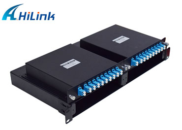
Half-sized LGX Cassette DWDM MUX DEMUX
A key advantage of DWDM is that its protocol and bitrate are independent. DWDM-based networks can transmit data in IP, ATM, SONET, SDH, and Ethernet. Therefore, DWDM-based networks can carry different types of traffic at different speeds over an optical channel. Voice transmission, email, video, and multimedia data are just some examples of services that can be simultaneously transmitted in DWDM systems. DWDM systems have channels at wavelengths spaced with 0.4nm or 0.8nm spacing.
DWDM is a type of Frequency Division Multiplexing (FDM). A fundamental property of light states that individual light waves of different wavelengths may coexist independently within a medium. Lasers are capable of creating pulses of light with a very precise wavelength. Each individual wavelength of light can represent a different channel of information. By combining light pulses of different wavelengths, many channels can be transmitted across a single fiber simultaneously. Fiber-optic systems use light signals within the infrared band (1mm to 750mm wavelength) of the electromagnetic spectrum. Frequencies of light in the optical range of the electromagnetic spectrum are usually identified by their wavelength, although frequency (distance between lambdas) provides a more specific identification.
DWDM System Components
A DWDM system generally consists of five components: Optical Transmitters/Receivers, DWDM Mux/DeMux Filters, Optical Add/Drop Multiplexers (OADMs), Optical Amplifiers, Transponders (Wavelength Converters).
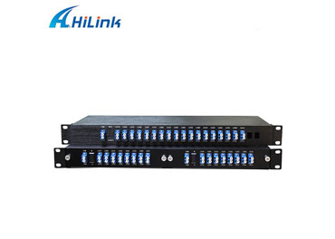
CWDM MUX DEMUX MODULE
Optical Transmitters/Receivers
Transmitters are described as DWDM components since they provide the source signals which are then multiplexed. The characteristics of optical transmitters used in DWDM systems is highly important to system design. Multiple optical transmitters are used as the light sources in a DWDM system. Incoming electrical data bits (0 or 1) trigger the modulation of a light stream (e.g., a flash of light = 1, the absence of light = 0). Lasers create pulses of light. Each light pulse has an exact wavelength (lambda) expressed in nanometers (nm). In an optical-carrier-based system, a stream of digital information is sent to a physical layer device, whose output is a light source (an LED or a laser) that interfaces with a fiber optic cable.
This device converts the incoming digital signal from electrical (electrons) to optical (photons) form (electrical to optical conversion, E-O). Electrical ones and zeroes trigger a light source that flashes (e.g., light = 1, little or no light =0) light into the core of an optical fiber. E-O conversion is non-traffic affecting. The format of the underlying digital signal is unchanged. Pulses of light propagate across the optical fiber by way of total internal reflection. At the receiving end, another optical sensor (photodiode) detects light pulses and converts the incoming optical signal back to electrical form. A pair of fibers usually connect any two devices (one transmit fiber, one receive fiber).
How does a waterproof touch screen monitor work?
Barcode Scanning Revolution: Exploring the Applications of Handheld Scanners Across Industries
Revolutionizing Electronics Manufacturing: The SMT PCB Smart Code Scanning Conveyor
What is a vacuum loader?
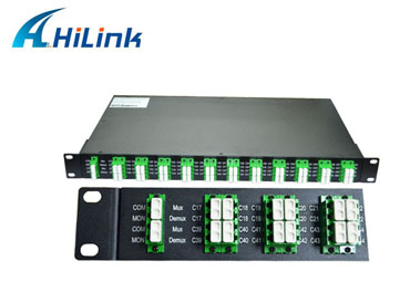
AAWG 40CH DWDM MUX DEMUX
DWDM systems require very precise wavelengths of light to operate without interchannel distortion or crosstalk. Several individual lasers are typically used to create the individual channels of a DWDM system. Each laser operates at a slightly different wavelength. Modern systems operate with 200, 100, and 50-GHz spacing. Newer systems that support 25-GHz spacing and 12.5-GHz spacing are being investigated. Generally, DWDM transceivers (DWDM SFP, DWDM SFP+, DWDM XFP, etc.) operating at 100 and 50-GHz can be found on the market nowadays.
DWDM Mux/Demux Filters
Multiple wavelengths (all within the 1550 nm band) created by multiple transmitters and operating on different fibers are combined onto one fiber by way of an optical filter (Mux filter). The output signal of an optical multiplexer is referred to as a composite signal. At the receiving end, an optical drop filter (DeMux filter) separates all of the individual wavelengths of the composite signal out to individual fibers. The individual fibers pass the demultiplexed wavelengths to as many optical receivers. Typically, Mux and Demux (transmit and receive) components are contained in a single enclosure. Optical Mux/DeMux devices can be passive. Component signals are multiplexed and demultiplexed optically, not electronically, therefore no external power source is required.
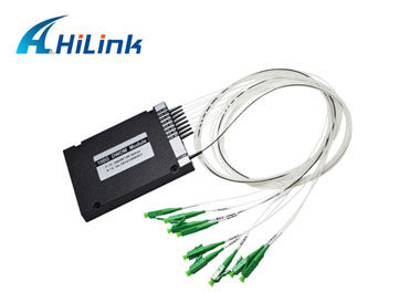
Filters of DWDM MUX/DEMUX ABS BOX
Optical Add/Drop Multiplexers
Optical add/drop multiplexers (i.e. OADMs) have a different function of "Add/Drop", compared with Mux/Demux filters. The dropped signal stream is passed to the receiver of a client device. The remaining optical signals that pass through the OADM are multiplexed with a new add signal stream. The OADM adds a new red optical signal stream, which operates at the same wavelength as the dropped signal. The new optical signal stream is combined with the pass-through signals to form a new composite signal.
OADM designed for operating at DWDM wavelengths is called DWDM OADM while operating at CWDM wavelengths is called CWDM OADM. Both of them can be found on the market now.
Optical Amplifiers
Optical amplifiers boost the amplitude or add gain to optical signals passing on a fiber by directly stimulating the photons of the signal with extra energy. They are "in-fiber" devices. Optical amplifiers amplify optical signals across a broad range of wavelengths. This is very important for DWDM system applications. Erbium-Doped Fiber Amplifiers (EDFAs) are the most commonly used type of in-fiber optical amplifiers. EDFAs used in DWDM systems are sometimes called DWDM EDFA, compared to those used in CATV or SDH systems. To extend the transmission distance of your DWDM system, you can choose from different types of optical amplifiers, including DWDM EDFA, CATV EDFA, SDH EDFA, EYDFA, Raman Amplifier etc.
Transponders (Wavelengths Converters)/OEO
Transponders convert optical signals from one incoming wavelength to another outgoing wavelength suitable for DWDM applications. Transponders are Optical-Electrical-Optical (O-E-O) wavelength converters. A transponder performs an O-E-O operation to convert wavelengths of light, thus some people called them "OEO" for short. Within the DWDM system, a transponder converts the client optical signal back to an electrical signal (O-E) and then performs either 2R (Reamplify, Reshape) or 3R (Reamplify, Reshape, and Retime) functions. The figure below shows bi-directional transponder operation. A WDM transponder is located between a client device and a DWDM system. From left to right, the transponder receives an optical bit stream operating at one particular wavelength (1310 nm). The transponder converts the operating wavelength of the incoming bitstream to an ITU-compliant wavelength. It transmits its output into a DWDM system. On the receive side (right to left), the process is reversed. The transponder receives an ITU-compliant bitstream and converts the signals back to the wavelength used by the client device.
Transponders are generally used in WDM systems (2.5 to 40 Gbps), including not only DWDM systems, but also CWDM systems. And WDM transponders (OEO converters) can come with different module ports (SFP to SFP, SFP+ to SFP+, XFP to XFP, etc.).
2994
0
6


Comments
All Comments (0)